Archives
Archive: Sep 2017
Car Sound Systems
Leave a CommentWritten by Tony Harris, September 22, 2017
Don’t you think the quality of car sound systems today is quite phenomenal? They are very compact units and capable of high volume and low distortion. How do they do it? You’d think you’d have to lug a trailer on the back full of amplifiers to get that type of sound quality.
The fundamental components that are doing the work in today’s amplifiers are transistors. The transistor gets its name from the combination of ‘resistor’ and ‘trans’. Basically it is just a resistor that we can vary. We can vary it from a short circuit to an open circuit. If you recall from some science or physics class years ago, you will know that the loss in a resistor is I2R: where I is the current in Amps and R is the resistance in Ohms. So if the resistance is 0 then the loss is the current squared times zero, so it’s zero loss. Now if the resistance is open (infinite) then no current can flow so again the loss is zero. So if we use a transistor in only two states; open or short, there is no loss and therefore, very efficient.
Car sound systems use a type of sampling technique, whereby they sample the input signal and effectively digitize it. Then they amplify it, but because they are now amplifying a digital signal it is either full on or full off – very efficient. After it is amplified they use a filter to reconstruct the analogue signal. The end result is it sounds great, but is very efficient so doesn’t dissipate a lot of heat and can be very small.
So why don’t we use this technique for high frequency amplifiers for ultrasonic and communication applications? The difficulty with this technique is that you have to switch the amplifier much faster than the frequency of the signal that you are amplifying. For audio signals this is not a problem but as we move into the high KHz and MHz region this pushes the state of the art of the capability of the transistors.
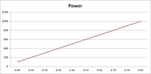
However, here at E&I using fast devices and interleaving techniques, we are pushing the frequencies higher and higher. We have our 1000S04 which is capable of 1000 watts of instantaneous power from 10 KHz up to 400 KHz. We also have 500S06 which is capable of 500 Watts 20 KHz to 600 KHz.
Before the end of June we will be at 1 MHz and then go beyond.
E&I is the leader in this technology, which will become the standard for ultrasound systems.
The Secret of the S-Series
Leave a CommentWritten by Tony Harris, 2nd September 2017
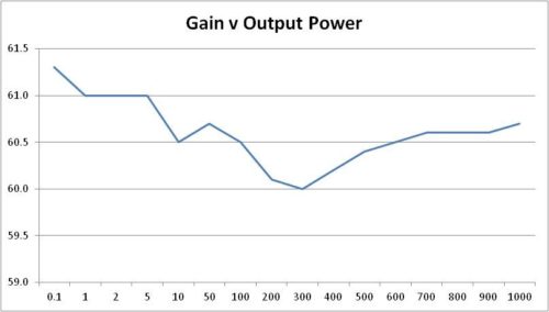
Someone was asking me the other day; how we are able to get such high switching rates on the large Fets that we use in our S-Series to enable us to achieve 1000 watts over a 600 KHz bandwidth. It is a good question, if you look at the performance of linearity, bandwidth and flatness you think that we were switching at over 3 MHz. Actually, in the 1000S04 we only switch at 1.6 MHz. But, then we use the technique, common in switch mode power supply design, to interleave the two halves of the H bridge. This enables us to mimic the performance that one would expect by from switching at 3.2 MHz.
KHz
So that’s the secret. We are looking to interleave in quadrature and so further push the frequency while maintain the excellent linearity and harmonic performance.