
Resource Center
This section provides a variety of technical resources and tools to help familiarize our customers on all aspects of our products and our industry. If you have any trouble finding the information you’re looking for, please don’t hesitate to give us a call at 585-214-0598.
Here you can find:
- Application Notes & Technical Articles
- Specifications & Terms
- Useful RF Formulae & Tools
- Industry Websites – supporting the markets & industries we serve
- FAQ section
- Application Notes
-
Specifications & Terms
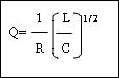
Q
The definition of Q, along with some helpful advice
When one thinks of Q one thinks of that upper class British technocrat explaining how the latest weaponry gadget works, to a disinterested James Bond. Who, himself, is more interested in contemplating how to uncover his next female spy. If you want more of that, I am afraid you will have to go elsewhere. We are not here to discuss what might impede fact or fictional relationships, but rather to discuss the real and imaginary relationships of impedances. Q: initially stood for ‘Quality Factor’. This was due to the fact that it was first used to describe the energy storage properties of a circuit in relation to its energy dissipation properties.
Now it is just Q, a dimensionless number. In fact one must be careful not to refer to it as ‘quality factor’ especially around management types. One could just imagine Dilbert proudly telling ‘Pointy-Hair’ that he has just designed an amplifier circuit that has a very low quality factor and promptly getting fired! The next day, as if on a crusade, ‘Pointy-Hair’ starts putting up motivational posters all around the engineering building: ‘Increase the quality factor of your circuit by 100%’. It would become part of management review and a strategic goal… Stranger things have happened.

But where Q really comes into its own is in terms of bandwidth. If bandwidth is f2-f1 then:Where f0 is the center frequency.
It is now obvious why we may want to design a circuit with a low Q. As we can see from the first equation (or elementary filter design rules) it will mean greater loss. However, for most circuits we want low Q.
(N.B. If we are talking about an element such as an inductor or capacitor we always want a high Q, as a low Q element would be indicative of parasitic resistance.)
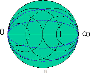
Another useful way of looking at Q is on a Smith Chart.
The blue lines indicate a constant Q. If you want to have a circuit with a Q below a certain value, then you must ensure that the transformation does not go outside the Q circle.
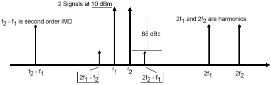
Third Order Intercept
What are third order products?
It is in the frequency domain. Third Order products are the intermodulation distortion products between the one of fundamental signals and the harmonic of the other signal.
Consider the diagram below:
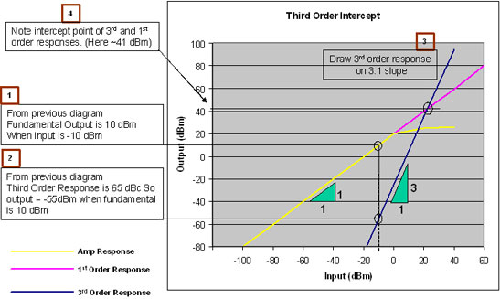
To plot the Third Order Response follow Steps 1 – 4 illustrated below:
A Good Match
A good match means that the output of one element is matched to the input of another to achieve maximum Power Transfer.
However, this is one place that one might help.
Consider the flow of water through a pipe…
- Water pressure is analogous to voltage
- Water volume is analogous to current
- Pipe diameter is analogous to resistance
- If you take the output of one pipe and put it against the input of one with a smaller diameter you will maintain your pressure but lose volume. If you put it against a pipe with a larger diameter you will not lose volume but you will lose pressure
For maximum power transfer the input and output impedances must be matched.
Now for some Maths (urrrgh)…
Consider the circuit below:
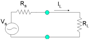
Now Current into the load is IL

Current Power in to load is PL
For maximum power
RL=RS
You don’t believe us?You are going to have to look at some calculus!
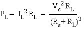
So if PL = IL2 RL
And for maximum power

And PL = IL2 RL = Vs2 RL (Rs+ RL)-2
Then
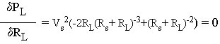
So: (Rs+ RL)-2 = 2RL(Rs+ RL)-31 = 2RL(Rs+ RL)-1
2RL = Rs+ RL
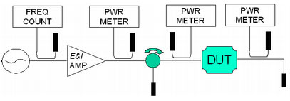
Rs= RLThe Basic RF Bench
All system impedances are 50 Ω.
A 50 Ω load is equal to a cable with a 50 Ω characteristic impedance infinitely long.
-
Useful Links
Below are links to some resourceful websites relevant to our industry and markets
-
RF Formulae
Useful RF Formulae
- Return Loss = 10Log10 (Preflected/Pforward)
- Reflection Coefficient = VR/VF
- Return Loss = 20Log10
- VSWR = (1 + p) / (1 – p)
- p = (VSWR – 1) / (VSWR + 1)
-
FAQs
Below you will find answers to some of our most commonly asked questions. If you’re unable to find the answer you’re looking for, please don’t hesitate to Contact Us or give us a call at 585-214-0598.
-
LabVIEW
Many thanks to Dr. Spiros Kotopoulis BEng(Hons), PhD of Department of Physics and Technology, University of Bergen, Norway, for doing this work and kindly allowing us to offer it to our customers.
- Log countless hours of data
- Calculate VSWR
- Pf and Pr Readbacks
- Displays Reflected power limits
Please Contact Us for more details
-
Information Video
E&I Amplifiers in action…
Check out our YouTube channel for more E&I videos
E&I Switchable Transformer
E&I’s Locked On series of switchable impedance transformers enable you to transform the 50 ohm input impedance of the amplifier, to drive higheror lower impedances ranging from 6 to 800 ohms, over the entire frequency range of 500 KHz through 5 MHz.
ENI Amplifier
UIA Presentation


